Hi there, thanks for stopping by.
My name is George and I have developed this website to showcase my electronic projects, along with the coding sources that I
have used, or created, to run them. Initially I will be working with both the Raspberry Pi 3 and the Pi zero boards using the 'Python' programming language making
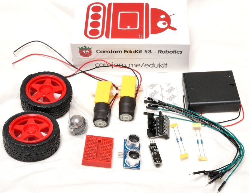
use of the components from the 'CamJam' series of kits.
Later, progressing on to using 'Python 3', to create my own scripts, to run my creations. At some stage I will also be working with the 'Arduino' platform using the Arduino Uno, Arduino Nano, Adafruit Trinket and the Adafruit Pro Trinket. Initially this will be making use of the literature that accompanies the 'Arduino Starter Kit', which will give me a sound footing to develop my oxn projects.
Finally, I would like to build some of the fantastic projects available on the 'Hackster' and the 'Instructables' platforms, which are all open-source projects.
- Your Raspberry Pi
- 400 Point Breadboard
- 1 x Red LED
- 1 x Yellow LED
- 1 x Green LED
- 3 x 330 Ohm Resistors
- 4 x M/F jumper wires
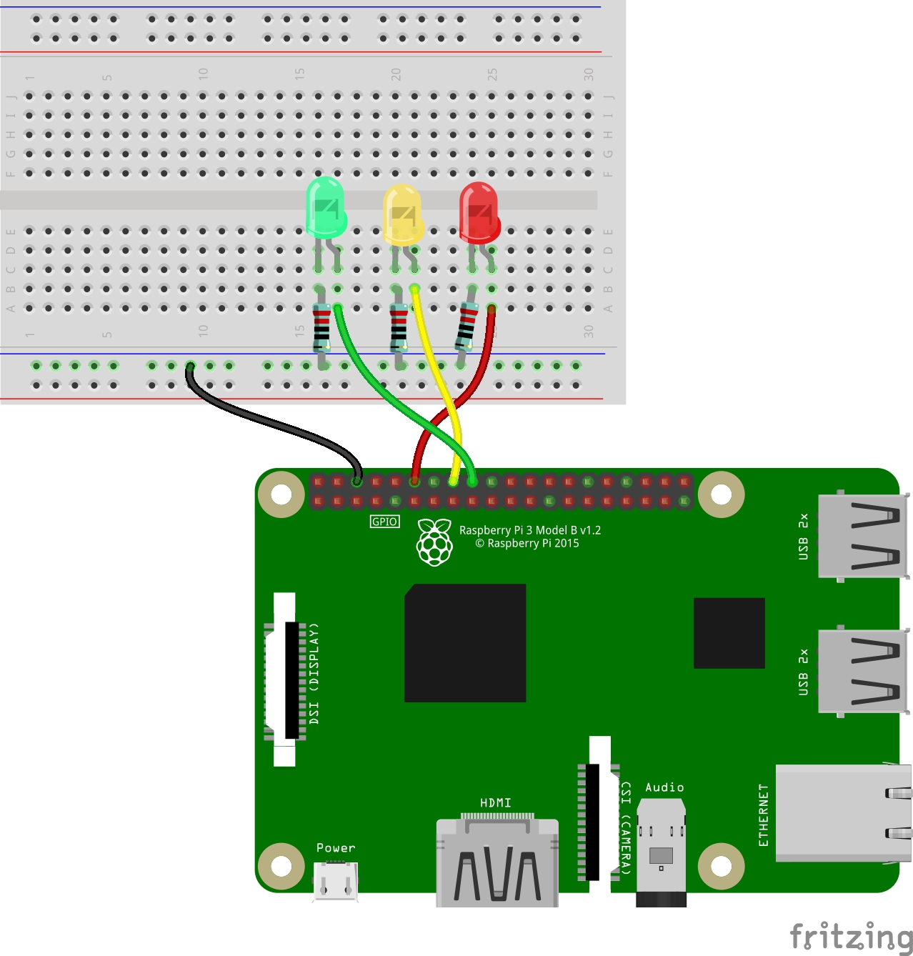
While you can build the circuit with the Pi turned on, it is best to turn it off at this stage.
You will be using one of the (GND) pins to act like the ‘negative’ or 0 volt end of a battery.
The ‘positive’ ends of the battery will be provided by three of the other GPIO pins, one for each of the three LEDs. You will be using the pins marked 18,
23 and 24 for the Red, Yellow and Green LEDs respectively. When they are ‘taken high’, which means they output 3.3 volts, the LEDs will light. The power
for each LED will be provided by the Pi, from GPIO pins 18, 23 and 24. You can control them from Python, meaning you can make the GPIO pins supply either
0 volts (off) or 3.3 volts (on).
There are in fact three separate circuits in the diagram. Each one consists of the power supply (the Pi), an LED that lights when the power is applied, and a resistor to limit the current that can flow through the circuit. Each circuit is going to share a ‘common ground rail’. In other words, you will be connecting all of the circuits to the same ‘ground’ (0 volts) pin of the Raspberry Pi. You are going to use the second row up from the bottom of the breadboard. Remember that the holes on the two top and two bottom rows are all connected together? So, connect one of the Jumper wires from the third pin from the left on the top row of the Pi to the second row up of the breadboard, as shown in the diagram (the black wire).
Next push three LEDs legs into the breadboard, with the long leg on the right as shown in the circuit diagram. Then connect the three 330Ω resistors between the ‘common ground rail’ and the left leg of the LEDs. You will need to bend the legs of each of the resistors to fit, but please make sure that the wires of each leg do not touch one another. Lastly, using three Jumper wires, complete the circuit by connecting pins 18, 23 and 24 to the right-hand leg of each LED. These are shown here with the orange, yellow, and blue wires.
You are now ready to write some code to switch the LEDs on.
On your Pi, open the Python3 IDLE, create a new text file and save it as 3-blink-forever.py. Either type out or copy and paste the code, in the box to the right.
Run the code by selecting the Run Module menu option, under the Run menu item, or you can just press the F5 key. You will see the three LEDs turn on then turn off forever, or until you press “Ctrl+c”. If there is an error in the code, change the code and resave it. Re-run to check that you have corrected the error.
# CamJam Edukit 1 - Basics
# Worksheet 3 - Making LEDs blink with Python
# Import Libraries
import time                   # A collection of time related commands
from gpiozero import LED      # The LED functionality from GPIO Zero

# Set the pins 18,23 and 24
red = LED(18)
yellow = LED(23)
green = LED(24)

# Loop forever (as true is always true)
while True:
# Turn LEDs on
print("The LEDs are now on")
red.on()
yellow.on()
green.on()

# Wait for 1 second
time.sleep(1)

# Turn the LEDs off
print("The LEDs are now off")
red.off()
yellow.off()
green.off()

# Wait for 1 second
time.sleep(1)

Hi there, thanks for stopping by.
My name is George and I have developed this website to showcase my electronic projects, along with the coding that I have created to run them.
Initially I will be working with both the Raspberry Pi 3 and the Pi zero boards using the 'Scratch' programming language, later, progressing on to using 'Python 3'. At some stage I will also be working with the 'Arduino' platform using the Arduino Uno, Arduino Nano, Adafruit Trinket and the Adafruit Pro Trinket.